Main Components of HZP40 Bridge Girder Segment Lifter
Main Components of HZP40 Bridge Girder Segment Lifter
This article is also for the HZP40 segment lifter for Guangzhou Metro Project.
Middle Outriggers
1. Middle outriggers are the key parts of the bridge girder launcher, which main function includes bearing, jacking and driving the bridge girder launcher to move forward and pass trough the span.
2. Bogie of middle outriggers is connected with main structure frame and the lower track of main structure frame is set on the carrier rollers on the bogie, which is advantage for main frame to slide in longitudinal direction.
3. Carrier rollers are installed on the both sides of outrigger bogie, main center distance is 1390mm and it walks with wheels.
4. Longitudinal moving mechanism of outriggers lies in the longitudinal moving tracks of main structure frame. The working principle is that longitudinal moving oil cylinder will jacking push the holes of longitudinal moving plate to realize the moving forward of the overall bridge building crane. In the front of oil cylinder there is equipped with longitudinal sliding segment and its end will be installed on the bogie of outriggers. Flexible actions of oil cylinder will drive the main structure frame to move forward and backward during the longitudinal moving of sliding segment.
5. Transverse moving mechanism of outriggers is set on the top of bogie of middle outriggers and column. Its working principle and process are similar with traveling system in longitudinal direction.
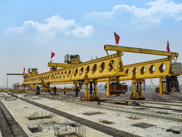
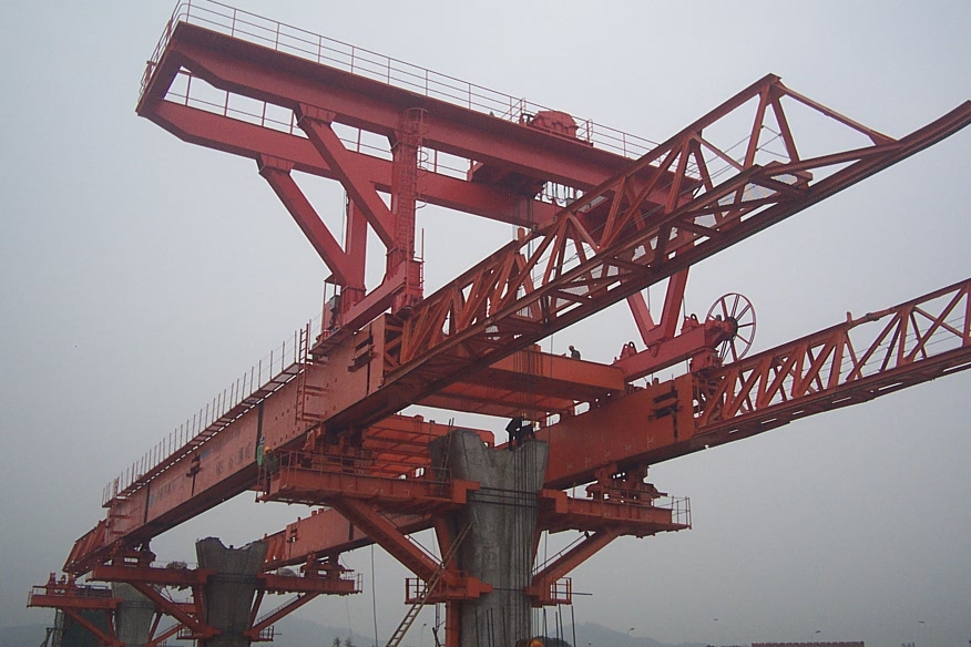
Main Beam
1. The structure of main beam of HZP40 bridge girder launcher is in box type, connected with high-tension bolts inside. The length of main beam is about 45m. The main beam is in simple structure, high rigid, mature fabricating technology, convenient installation method and etc.
2. There is a track for overhead lifting trolley at the upper cover plate of main beam and longitudinal moving slider for lower cover plate.
3. There are dis-mountable connection beams at the both ends of main beam.
Guide Beam
1. Total length of guide beam is 22m.
2. At the top of truss girder guide beam there are overhead tracks for lifting hoist. And longitudinal sliding tracks are at the bottom. Structure of guide beam is in simple structure and definite stress. At the bottom of guide beam, walkway is arranged, which is convenient for bridge building construction. Bumper post is connected with the end of guide beam.
Overhead Lifting Hoist
1. Overhead Lifting Hoist is composed of trolley, crane moving system, gantry frame, lifting system, hydraulic system and electrical system.
2. Overhead lifting hoist is installed on the main beam, which can travel in the scope of ±0.5m cross section of the bridge girder launcher. Crane moving mechanism is under the main beam, its track gauge is 6m and wheel thread is 4.8m. Main beam of overhead lifting hoist is in box structure.
3. Moving system of overhead lifting hoist include four same bogies in 1/2 drive method. Its traveling speed without load id 0-15m/min. There are rail clamping device equipped to match up the bridge building crane to brake or stop, so that it will be more efficient to control the brake system.
ZZHZ Related Products:
Gantry Crane, Overhead Crane, Bridge Girder Launcher, Girder Transporter, Concrete Batching Plant, Concrete Mixer and etc.
See more, please visit our website: zzhz.com
Email: zzhz114@gmail.com Tel: 86-371-68000000